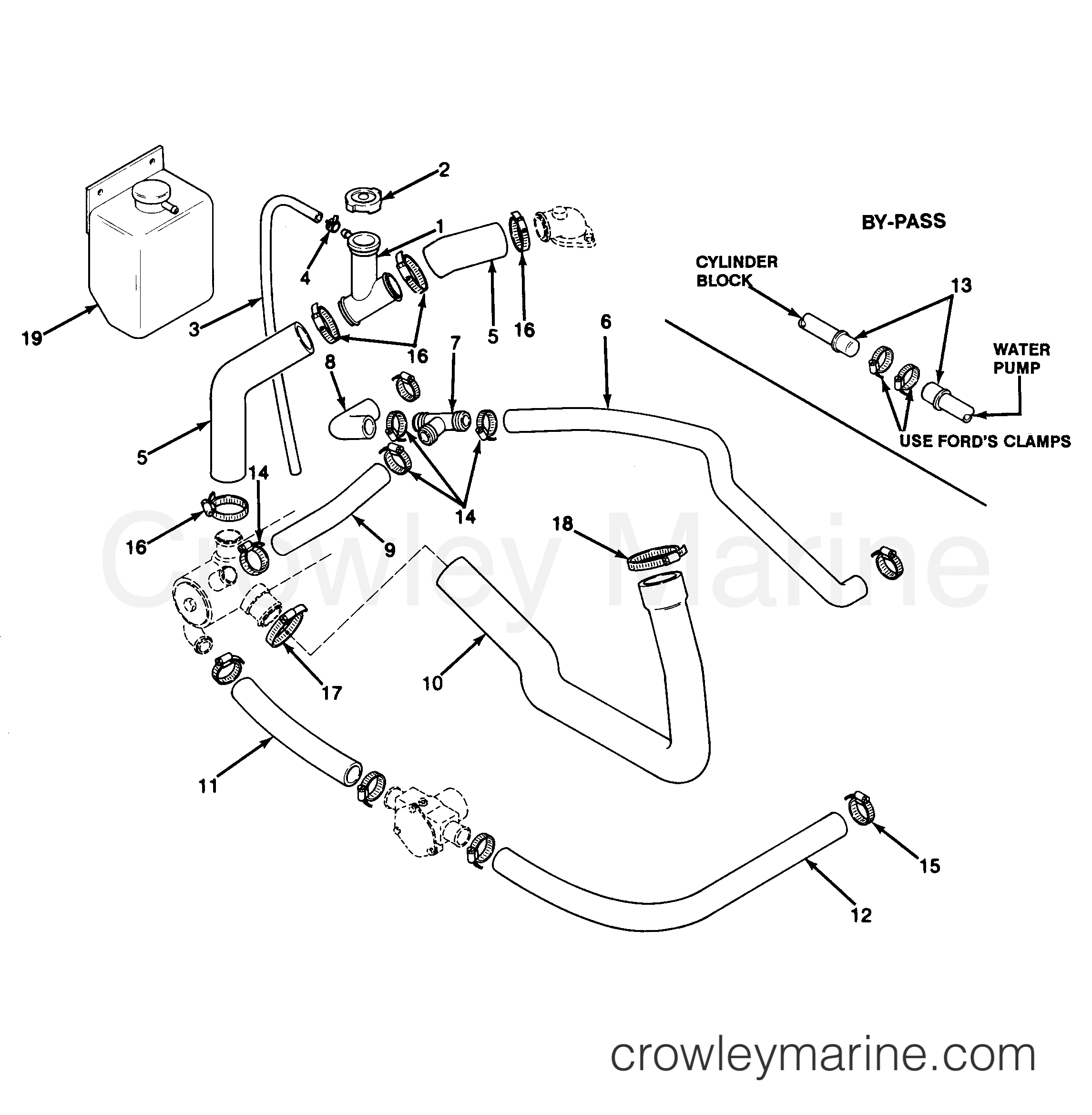
Marine Engine Cooling System Diagram
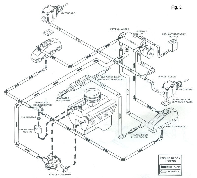
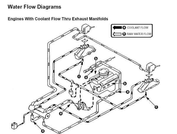
Marine engine cooling system diagram. However in 2002 the decision was made that going forward all new designs would be done while including a warm manifold cooling system unless this was just not possible. Marine engine cooling system diagram - thank you for visiting our website. 41 Keel Cooling - CommercialWork Boat applications traditionally incorporate keel cooling See diagram 1.
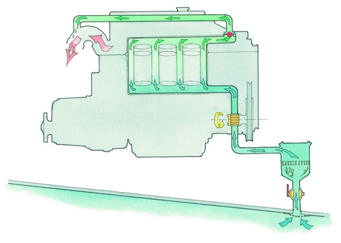
Main Concerns Task List Indirect Cooling Fresh Water Cooled Direct Cooling Keel Cooling 1 Clean Thruhull of Anti-Foul Paint and Marine Growth 2 Check Emergency Plug Tied to Every Seacock 3 Check Seacock OpensCloses Smoothly 4 Inspect Raw Water Strainer 5 Service Raw Water. Engine Diagram Courtesy Marine Diesel Engines by Nigel Calder The core of marine diesel engines are the combustion chambers. One for cooling the cylinder jackets cylinder heads and turbo-blowers.
This fresh water is circulated through the engine and through a heat exchanger. 454 sensor wiring diagram wiring diagram pictures u2022 rh mapavick co uk Cooling System Flow Diagram GM Engine Cooling System Diagram. This will cause the engine to overheat in hot weather.
Volvo penta cooling systems. MerCruiser 260 gm 350 v-8 1982-1986 standard cooling system parts. It is divided into two separate systems.
From the thousands of photographs on the internet with regards to marine engine cooling system diagram selects the best libraries using greatest quality just for you and now this photographs is usually considered one of photographs collections in our greatest pictures gallery concerning Marine Engine Cooling System DiagramI hope you may think its great. The outlet temperature of the main engine cooling water is kept constant at 85-95 by means of temperature control valves by mixing water from the two central cooling systems ie. Buy a genuine Mercury Quicksilver or aftermarket part.
Marine raw water cooling system diagramDiesel Engine Cooling System. And finally we upload it on our website. This video explains how the cooling system w.
The fresh water in this system absorbs the heat of the engine. The engine cooling pump is the heart of the marine engine supplying a continuous flow of raw water to maintain temperatures consistent with the demanding engine performance.
454 sensor wiring diagram wiring diagram pictures u2022 rh mapavick co uk Cooling System Flow Diagram GM Engine Cooling System Diagram.
This will cause the engine to overheat in hot weather. Cooling Pump for Pleasurecraft Engines by Sherwood Pumps. Marine raw water cooling system diagramDiesel Engine Cooling System. The cooling water in the system to be treated with chemicals. Cooling System Coolant DEAC - Change SMCS Code. A connecting rod transfers the motion of the piston to the crankshaftThe crankshaft converts the up and down motion to useful rotation. 41 Keel Cooling - CommercialWork Boat applications traditionally incorporate keel cooling See diagram 1. In the old days many marine engine cooling systems were of the raw-water variety meaning simply that they relied on pumping whatever water the boat was floating in through. One for cooling the cylinder jackets cylinder heads and turbo-blowers.
The fresh water in this system absorbs the heat of the engine. Cooling System With Cross Flow Radiator And Separate Surge Tank 1 Radiator cap. The cooling water in the system to be treated with chemicals. Cooling System Coolant DEAC - Change SMCS Code. And finally we upload it on our website. In each chamber a piston goes goes up and down based on the combustion of diesel fuel. In the old days many marine engine cooling systems were of the raw-water variety meaning simply that they relied on pumping whatever water the boat was floating in through.








Post a Comment for "Marine Engine Cooling System Diagram"